In discrete manufacturing, the gap between feeding parts, checking them with cameras, and picking them up with robots is often where production speed dies. A new technical breakdown from automation equipment maker FIDER explains how its intelligent feeder system closes that gap, using synchronized communication and closed-loop control to keep assembly lines running at peak output.
SHENZHEN, GUANGDONG, CHINA, October 30, 2026 /EINPresswire.com/ — High-speed discrete manufacturing demands more than independent machines working side by side; it requires raw material feeding, optical inspection, and robotic manipulation to operate as one continuous, coordinated process. Deploying a Production Line Integrated Intelligent Feeder directly addresses the synchronization bottlenecks that typically emerge when separate automation subsystems are stitched together into a production line. Treating feeding hardware, vision cameras, and robotic arms as disconnected units inevitably introduces communication lag, camera motion blur, and starved assembly stations. By establishing deterministic communication handshakes and closed-loop control protocols, automated manufacturing lines can hold steady pacing and push net throughput to its maximum.
The Three-Pillar Architecture of an Intelligent Feeding Cell
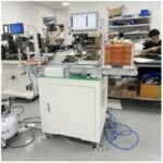
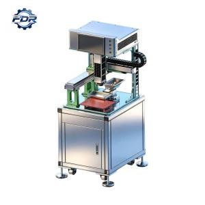
At its core, an automated feeding workstation is a closed-loop mechatronic system built on three tightly coupled functional pillars: the multi-axis vibration feeder, the machine vision guidance computer, and the high-speed robotic manipulator. Each pillar carries a specialized operational role, yet the overall efficiency of the cell rests entirely on how well they coordinate in real time.
These three pillars interact through clearly defined responsibilities: – The multi-axis vibration feeder: Agitates, disperses, and flips bulk components across a flat pick surface using programmable voice-coil or electrodynamic actuators. – The machine vision system: Analyzes illuminated part contours, verifies component orientation, and calculates pick coordinates relative to the robot coordinate frame. – The robotic manipulator: Executes high-speed kinematic trajectories to retrieve oriented components and place them into downstream conveyor nests or assembly fixtures.
When these systems run without tight hardware synchronization, the cell suffers severe pacing inefficiencies. The robot sits idle waiting for vision coordinates, or cameras fire while parts are still vibrating, producing blurred images that trigger false rejects. Unifying these subsystems under a central controller transforms them into a responsive, self-regulating assembly cell.
Communication Protocols and Hardware Handshakes
Wiring three distinct automation components into a single integrated workstation demands robust digital communication interfaces. Industrial control engineers rely on a mix of deterministic fieldbuses, serial links, and optical digital input-output lines to manage system handshakes.
A properly architected feeding cell uses structured communication layers: – High-speed Ethernet TCP/IP or industrial fieldbuses, such as EtherCAT or PROFINET, link the vision computer to the robot motion controller, transmitting structured coordinate arrays in milliseconds. – Dedicated RS232 serial interfaces connect the feeder controller to the master programmable logic controller, enabling dynamic updates to vibration frequency, amplitude, and directional parameters. – Hardwired 24V DC optically isolated digital lines deliver microsecond-level timing triggers for emergency stop loops, strobe illumination, and vibration pause signals. – Hardware encoder inputs monitor downstream conveyor belt speeds, synchronizing robotic placement trajectories with moving assembly lines.
Standardizing communication protocols prevents data packet collisions and guarantees deterministic response times across every automation element.
Eliminating Camera Blur Through Vibration Gating
Capturing sharp, high-contrast images of miniature parts demands eliminating relative motion between the component and the camera sensor during exposure. If the vision camera triggers while the multi-axis feeder platform is still vibrating, the optical blur that results distorts component edges, causing failed contour matching and dropped pick cycles.
Advanced feeding cells implement a microsecond vibration gating sequence: – The feeder controller receives an image acquisition request from the vision computer and immediately cuts drive coil power. – Within ten to fifteen milliseconds, the mechanical vibration dampens completely, and the feeder outputs a settled hardware signal. – The vision system activates high-intensity LED backlight or coaxial strobes for two to five milliseconds to capture a freeze-frame image. – Immediately following exposure completion, the controller re-energizes the feeder coils to resume part agitation.
This rapid gating sequence removes optical motion blur without causing noticeable pauses in overall part feeding, maintaining continuous production cadence while preserving micron-level optical inspection accuracy.
Dynamic Coordinate Buffering and Trajectory Queuing
Maximizing robotic pick throughput requires feeding coordinate data to the motion controller in continuous, buffered queues. In a high-speed picking cell, a single vision snapshot typically identifies five to fifteen correctly oriented components on the feeder surface simultaneously.
Pipelined coordinate buffering works through a streamlined sequence: – The vision computer processes the captured frame and compiles an ordered FIFO coordinate queue containing X-Y positions, planar rotation angles, and pick priority rankings. – This data array transmits to the robot controller via high-speed Ethernet sockets in a single data burst. – The robot motion planner calculates optimal point-to-point trajectories, picking components sequentially from the coordinate queue without pausing between strokes. – While the robot executes picks from the active queue, the vision processor analyzes subsequent camera frames in the background.
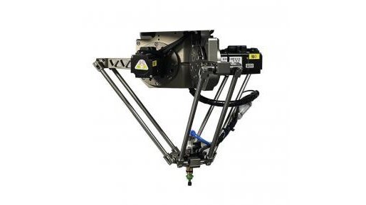
Deploying a Production Line Integrated Intelligent Feeder with coordinate queuing eliminates communication latency pauses, enabling parallel Delta robots to sustain throughput between 3,000 and 4,500 parts per hour.
Closed-Loop Hopper Replenishment and Density Control
Keeping optimal component density on the feeder platform is critical for steady pick rates. If too few components occupy the tray, the robot faces part starvation. Conversely, overloading the plate with excess bulk parts creates overlapping clusters that obscure vision recognition and reduce pickable yields.
Automated closed-loop replenishment maintains balanced part distribution: – The vision computer continuously tracks the total number of recognized components within the field of view after each robotic pick. – When the active part count drops below a pre-programmed lower threshold, the controller sends an activation signal to an upstream bulk storage hopper. – The bulk hopper vibrates for a calibrated duration, metering a controlled batch of fresh components onto the feeder tray. – Digital load cells mounted beneath the feeder platform provide secondary weight feedback, verifying that bulk replenishment remains within safe mechanical limits.
Automation equipment manufacturers like FIDER integrate closed-loop hopper controls directly into their intelligent feeding systems, ensuring stable part presentation without manual operator intervention.
Fault Recovery and Line Conveyor Pacing
Industrial manufacturing lines frequently experience upstream starvation or downstream backlogs that require automated speed pacing and fault recovery. An intelligent feeding cell must adapt dynamically to surrounding line conditions without generating system errors.
Automated fault recovery protocols safeguard continuous operation: – Downstream pacing: If downstream assembly stations back up, the feeding cell pauses robotic placement and slows feeder agitation to prevent component wear. – Vacuum pick failure recovery: If an end-effector vacuum sensor detects a dropped component, the controller flags the coordinate, retries the pick, or discards the flawed part into a reject chute. – Unpickable part clearance: If unpickable components accumulate on the feeder surface, the system executes an automated forward sweep pulse, clearing the tray into a return chute. – Telemetry logging: Real-time operational data logs pick success rates, cycle times, and error frequencies, providing line engineers with actionable predictive maintenance data.
Integrating a Production Line Integrated Intelligent Feeder provides modern factories with the responsive, closed-loop automation needed to maintain peak line efficiency. To review intelligent feeder integration protocols or discuss multi-axis feeding architecture for your production line, explore comprehensive technical specifications at https://www.fdrautomation.com/ to schedule an engineering consultation.
FIDER
FIDER
Also worth a look: Delta robot cells swap mechanical tracks for software to handle high-mix assembly and Flexible Feeder vs. Vibrating Bowl: The Changeover Math That Decides.
Why it matters: This technical approach shows that the next leap in factory productivity isn’t just faster robots, but smarter orchestration of the machines that feed and inspect them. For manufacturers, eliminating these micro-delays translates directly into higher throughput and lower error rates on the line.