Parts feeding is the single biggest reliability factor on any automated assembly or packaging line — and the choice between two competing technologies can shape uptime, scrap rates, and tooling budgets for years. For manufacturing engineers weighing their options, a Flexible Feeder offers programmable agility that stands in sharp contrast to the fixed physical mechanics of a traditional vibrating bowl feeder. Vibrating bowls remain the historical standard for dedicated, high-volume production, but modern manufacturing keeps pushing toward shorter product lifecycles, frequent engineering revisions, and complex miniature components. Picking between the two approaches means weighing part geometry, surface fragility, batch changeover frequency, and long-term capital economics.
Operating Principles and Mechanical Differences
The fundamental distinction between flexible feeding systems and vibrating bowl feeders comes down to how parts reach the correct orientation. A traditional vibrating bowl feeder depends on mechanical sorting: electromagnetic coils vibrate a spiral metal bowl, pushing parts upward along an internal inclined track. As components climb that spiral path, custom-machined mechanical wiper blades, cutouts, narrowing tracks, and gravity traps physically filter them. Parts already in the desired orientation continue through to the outfeed track, while misoriented parts are deflected off the track and tumble back to the bottom of the bowl.
Also worth a look: Government Business Results hires veteran B2G marketer Allan Rubin as VP to scale public sector services and Delta robot cells swap mechanical tracks for software to handle high-mix assembly.
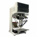
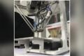
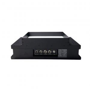
A modern Flexible Feeder, by contrast, separates mechanical agitation from part orientation. The system pairs a flat vibration plate driven by multi-axis voice-coil or electrodynamic actuators with an overhead machine vision system and a high-speed robot. Rather than forcing components through geometric obstacles, the flexible platform vibrates along three independent axes to scatter part clusters and flip components over. An overhead camera images the backlit plate, spots correctly oriented parts, and calculates their precise pick coordinates. The robot picks the ready components, while unpicked parts stay on the plate for further vibration pulses or return to a bulk hopper through recirculation chutes.
Part Geometry, Surface Fragility, and Jamming Risks
Component physical characteristics largely determine which feeding technology is technically viable. Vibrating bowl feeders run reliably only when components have consistent geometric asymmetry — a stepped diameter or offset center of gravity, for instance — that physical tooling can exploit. Delicate parts, however, suffer substantial wear in bowl feeders: surface scratching occurs as components repeatedly slide against metal bowl tracks and tumble over gravity reject steps, damaging polished decorative surfaces, optical coatings, or thin plating. Delicate terminal pins, lead frames, and stamped contact fingers risk mechanical bending when wedged against mechanical wiper blades. Thin stamped sheet metal parts frequently overlap and shingle, wedging between track walls and causing complete line stoppages. Oily, sticky, or electrostatically charged parts adhere to metal tracks, resisting gravity-based orientation and starving downstream assembly stations.
A Flexible Feeder eliminates these failure modes through gentle part handling. The agitation plate uses medical-grade polyoxymethylene, silicone, or antistatic coatings that absorb impact energy and prevent cosmetic blemishes. Because the platform is an open, flat surface without constrictive tracks, parts cannot become physically wedged or jammed. The system handles challenging geometries — symmetrical cylindrical pins, flexible rubber grommets, and delicate micro-springs among them — with zero risk of mechanical deformation or surface degradation.
Changeover Speed and Production Line Downtime
Changeover speed is another decisive operational contrast. In a high-mix manufacturing environment where product variants change daily or weekly, the mechanical rigidity of vibrating bowls creates substantial production downtime. Retooling a vibrating bowl feeder requires a skilled mechanical technician to physically unbolt the bowl, install a dedicated replacement bowl, and align outfeed tracks with downstream pick nests. Fine-tuning mechanical gates, air blow-off nozzles, and track clearances often takes two to six hours before steady feed rates are reached.
A Flexible Feeder completes product changeovers digitally in under three minutes: operators select a pre-configured component recipe from the touchscreen human-machine interface; the platform executes a brief automated purge vibration cycle, sweeping remaining parts into a collection drawer; the controller instantly loads new vibration frequency, amplitude, and directional parameters matched to the incoming component geometry; the machine vision system switches to the corresponding part contour inspection model and optical lighting settings; and the upstream bulk storage hopper dispenses the new component batch onto the feeder plate to begin production.
This digital workflow removes the need for specialized mechanical tooling technicians during changeovers, letting lean production lines execute multiple batch transitions per shift without sacrificing operating efficiency.
Total Cost of Ownership and Lifecycle Economics
Evaluating parts feeding equipment financially means examining total lifecycle expenditure, not just the upfront purchase price. A customized vibrating bowl feeder typically carries a lower initial purchase cost for a single dedicated component. That apparent cost advantage erodes quickly, however, when production programs involve multiple part variants or frequent engineering revisions.
Several recurring cost drivers shape bowl feeder economics: every minor component design change mandates re-machining, welding, or replacing the mechanical bowl, incurring substantial tooling costs and supplier lead times; warehousing dedicated spare bowls for each discontinued product variant consumes extensive facility storage space and capital; and production losses from recurring track jams, part shingling, and component scrap directly degrade manufacturing margins.
A Flexible Feeder represents a higher initial capital investment, owing to its multi-axis actuators, machine vision hardware, and precision robotic manipulator. Yet the system acts as a reusable manufacturing asset across multiple product lifecycles. When a component undergoes an engineering revision, the change requires only a software template update and minor camera exposure tuning. Over a three-year operating period in high-mix environments, the savings from eliminated retooling costs, reduced scrap rates, and recovered production uptime deliver a compelling return on investment.
Decision Criteria and Application Selection
Choosing the optimal feeding architecture requires matching equipment capabilities to production constraints. Manufacturing engineers should consider vibrating bowl feeders for high-volume, low-mix programs where millions of robust metal fasteners, standard hardware fasteners, or rigid plastic caps run continuously without design revisions for several years. In these dedicated environments, the low capital expenditure and high standalone feed rates of bowl feeders remain cost-effective.
Conversely, a Flexible Feeder is the superior choice for high-mix electronic assembly, automotive sensor packaging, medical device manufacturing, and precision cosmetics packaging. Facilities that produce delicate parts, handle frequent batch transitions, or manage multiple product variants benefit from programmable multi-axis vibration and optical guidance.
Automation equipment manufacturers such as FIDER engineer integrated flexible feeding systems that unite multi-axis vibration platforms with intelligent vision recognition and Delta pick-and-place robotics. These unified systems process component profiles ranging from 0.5 mm to 150 mm, delivering placement repeat precision of ±0.05 mm alongside high-speed sorting rates. Matching feeding technology to part vulnerability and production flexibility ensures uninterrupted manufacturing uptime. To evaluate component feeding feasibility or request sample testing for complex parts, review technical specifications at https://www.fdrautomation.com/ to schedule an engineering consultation.
FIDER
FIDER
Why it matters: As product lifecycles shorten and high-mix production becomes the norm, the feeding decision stops being a one-time equipment purchase and becomes a question of how often a line must adapt. The contrast between hours of mechanical retooling and minutes of digital recipe switching shows where hidden costs accumulate — and why engineers are rethinking the default bowl feeder for delicate, fast-changing parts.